


| FAQ #205 | |
  |
|
 |
'Throttle Potentiometer'? |
 |
What it does It measures the throttle valve angle and sends a proportionate voltage signal to the ECU. The ECU uses this information as a load signal and calculates the engine’s ignition and fuel system requirements. It is also used to recognise specific operating conditions, such as idle and full throttle, that need to be controlled. How it works: 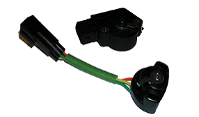 attached to the throttle body, it is an electromechanical device that converts the rotary motion/angle of the throttle shaft into an electrical signal that the ECU can understand. attached to the throttle body, it is an electromechanical device that converts the rotary motion/angle of the throttle shaft into an electrical signal that the ECU can understand.It is generally a three or four terminal device, one terminal is the electrical feed (generally five volts) and the other two terminals, being the output are connected to internal variable resistors. Two internal resistors are used to ensure that whatever the throttle position the ECU will have an exact measurement. The fourth terminal, which is not fitted on all throttle potentiometers, is an earth connection. The format of the two internal resistors varies, some manufacturers utilise opposite variance resistors, so as the throttle angle increases one resistor increases and the other decreases. Other manufacturers use two different value resistors, the first one has a very “steep” resistance “curve” and is used to measure low throttle openings, the other resistor has a very “shallow” resistance “curve” and is used to measure mid to full throttle openings, both these resistances cases will increase with throttle opening. Note: Before the introduction of full engine management, throttle potentiometers consisted of just two switches. One for full throttle and one for an idle position, they appear similar but they are operationally different. Ensure that you are fitting/testing the correct type. Reasons for failure: Constant throttle movement wears through the resistive wiper-tracks, the first 30 degrees of throttle movement is the area in which most wear failures take place. This usually results in flat spots or holes in acceleration or tick-over problems such as stalling. Other failures are due to the environment in which the potentiometer is located; it suffers from dirt, water and vibration damage as well as over-voltage damage due to wiring faults. Testing: A simple multimeter will highlight most faults. Check the voltage supply to the unit, it is generally five volts but a short to 12 volts is common fault on some vehicles. Check the voltage feed with the sensor connected so as to “load” the power supply; this should show up any poor connections on the feed side. Check the earth for a zero voltage reading. Check the voltage output at the idle position, compare this with OE specifications. Check the output of both resistors with both an opening and closing throttle, it is often best to do this from within the car and operate the throttle with your foot as this tends to be easier to control. Check the resistance throughout the range, paying particular attention to the first 30 degrees of movement as above. If the potentiometer is faulty, it usually shows up as an open circuit at one particular throttle opening, this can be difficult to spot. The ECU diagnostic function may or may not, as is often the case, record the fault. It is also good policy to “tap” the potentiometer with a screwdriver, or the like, when testing, to simulate vibration; this can show up track connection faults. Caution: The idle position of the sensor is critical, there is often a specific voltage setting that should be checked during any engine management system check. Any wear in the vehicle’s throttle linkage, mechanism or body will cause a misreading at the ECU which will result in a tick-over problem. |
| Views | 3426 (Unique 2058) |
| Member Rating : |  10.0 - 2 votes 10.0 - 2 votes |
| FAQ Posted by | C6Dave |
| Info | Created: 07 October 2009 Last Updated: 18 December 2015 |
 Posted by M2dis Posted by M2dis Posted by MGmike Posted by onthecut Posted by citroenroen1
Privacy Policy | Cookie Policy | Site Disclaimer | Contact Details | Warranty | Sitemap | C6 Insurance | Quick Facts | Re Call Info | Downloads | Error Codes
| Site and Graphics created by: C6Dave Forum Icons by Axialis Emotes by Seb | 
|
